I had a problem to solve. The VERY crudly drawn schematic I made in KiCad is how I solved it.
You see, I love discreet component projects and the use of transistors in those builds. No this is not to say that I am against things like Arduinos and Raspberry Pi SBCs. Quite the opposite in fact, I love them when the application can actually benefit from one of those devices being employed. This project could have used one of these, to be fair, but it would have been grotesque overkill to use an SBC on a project like this. (An “SBC” is a Single Board Computer and is essentially the whole system, albeit a little weaker than bigger machines, on a single circuit board)
I opted to see if I could come up with a way to use discreet components to build something that fit the following criteria:
simple design
small footprint
no programming required
doesn’t drain the batteries excessively
works on 12 vdc power
can detect when a 4 D cell array weakens to 5.4vdc
fires an alarm that latches on when triggered
is noticable and easy to notice when triggered
Some of these parameters came about after the fact as I would build something on the bread board and try it and then figure out that I needed something else to make it work like I wanted it to.
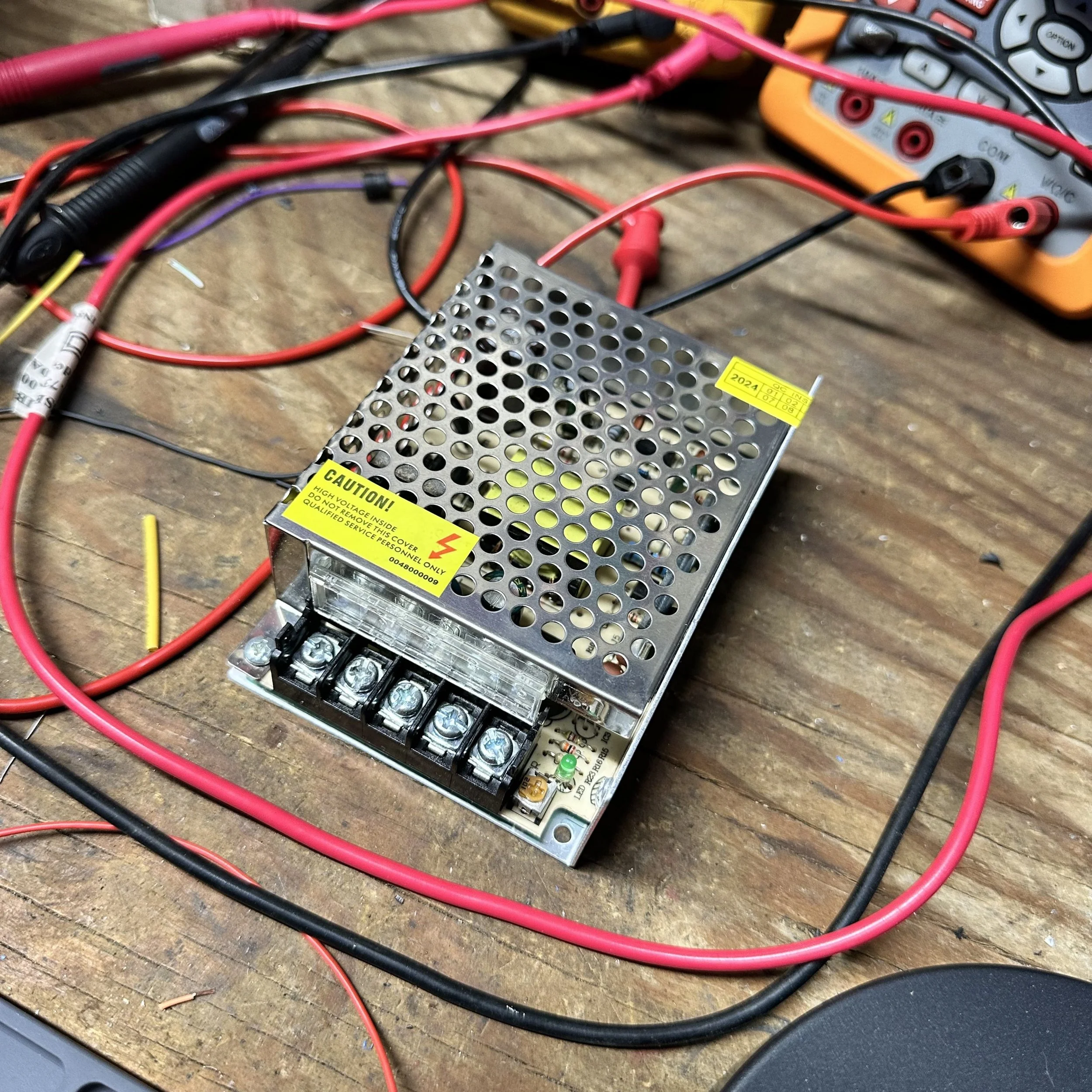
All good things start with a great power source. This is no different, this is a adjustable 12 vdc power supply. These are super stable and relatively cheap too. I don’t remember the price for this one, but it was very reasonable. This is also severely overkill for this project too. This whole project only draws about an amp max. Probably closer to 1/2 amp to be honest with the lion’s share of that being the LED display draw which is a little over 300mA of the whole thing. Regardless, this is what I bought so I used them. At least I have some room should I want to add something else later that uses 12vdc power…After making a few mistakes in getting some measurements by using one of my bench supplies, I realized I could simply power this one up and use it to do the tuning and then simply install it in the machine and use it to power the circuit too, this way there was no discrepancy in voltage and it worked like a charm.
Below is not the circuit I made for this project from but another one that I will be writing about. The point of this photo is to show you what I use to get my ideas out of my head. 1/4” grid graph paper is my favorite for this kind of work. It allows me to draw to scale (if I want) and it is easy on my eyes for some reason too. Can you figure out what the chip is that is in the below circuit by just looking at the surrounding circuitry? I bet you can if you do much discreet component building.
A quick disclaimer here, I use the term discreet component build pretty loosely here. The definition technically doesn’t involve integrated circuits, but I include any device that doesn’t require a program to make it work… That is why this project, in my opinion, is a discreet build even though it has a quad NAND gate chip in the middle of it as well as an opto-isolator package…
With that out of the way, let’s get to the theory of operation and why I did it like I did.
As you can see the board below, it meets the first two criteria right away. It is small and simple. The third criteria of no programming is not immediately evident since it has a DIP package chip on the board, but upon simple inspection this is also evident. The other criteria comes from the design itself and it will show up a little later.
Lets just go through how it works right quick.
The voltage regulator is obvious, I am using it to make the 5VDC refernce voltage for input A as well as the Vcc for the gate chip.
To get the “trip” effect out of the gate, I make one input high all the time and the other is watching for the input to go low. I chose a NAND gate which is a AND logic function with an inverter on the output to simply reverse the state of the output. This is because, I need to see when the voltage goes low and not high. A NAND gate will give a low output when both inputs are high and a high output in the rest of the possible conditions.
When the voltage of the batteries go down to 90%, the voltage is 5.4VDC and with the voltage divider, the gate gets 2.08 volts at this point. This is the trigger point for the gate, anything less than this number and the input flips to low.
When this happens, the output of the gate goes high (5VDC) and then flows to the base of the NPN transistor to bias it, but there is a little trick here too. I added a 100K ohm resistor and a 100uF capacitor to this circuit to add a time delay to the base being biased on. What this does is allows the circuit time to power up and all the voltages to stabilize before this transistor is triggered, preventing false high outputs upon power up.
The transistor fires the photo diode side of the opto-isolator with a couple of resistors to control current and drop some of the voltage from the power rail since this is on the 12VDC part of the circuit.
The output of the opto-isolator is wired to the gate of the SCR package through a voltage dropping resistor with a small cap to absorb any voltage spikes that might come down this line.
The SCR is simply wired in series with the LEDs and acts as a simple latching relay in this application. This insures that if the battery voltage dips below the set point at any time during the work day, the display will turn on and stay on till the batteries are replaced and the machine is powered off…at least that is how the machine should be responded to when this condition exists…
i could have probably left the opto-isolator out and just used the transistor to directly control the SCR, but I wanted to play with the opto-isolator to be honest and see if I could make it work. HaHa.
I really love using perf board to build my projects. It is the lazy mans way of making a PCB and it is also the impatient man’s way as well. There is no waiting to get to see my project come to life when I use perf board on the contray should I have designed my circuit board in KiCad and sent off the gerber files to make them. First I would have to finish learning how to make the designs in KiCad, then I would have to wait to get the boards in… Plus I only need two of these boards as well, so I didn’t have to do all that design work for a circuit board for just two units… The perf board can be had from Amazon for very reasonable money and it comes with header pins as well as the screw terminals you see on this board for making outside connections to the circuit. That is the exact place I bought these boards from, they come in a kit of stuff for about 20$ if memory serves me on this.
Another tip I am giving away for free is below. I draw isometric views of some of the parts for reference when assebling them. This keeps me from wiring them up backwards…most of the time… I got one of these SCRs backwards out of the gate for some reason and the leakage current make the LEDs glow dimly but I could tell something was off so I checked and sure enough, the anode and cathode were backwards… So yeah, it can help to have that 3D view when wiring it up if the lead arrangement is odd like it is here. You can also see where I drew the layout of the opto-isolator as well with the components physical layout next to the pins for reference. This really helps with DIP packages…
I started out using a transistor to fire the LED array to signal the battery was low, but this turned out to be unreliable to start with. The LEDs would not latch on and could turn back off with a transistor controlling them. This is why I opted to use a SCR as once it is fired “on”, it will stay in the “on” condition till you power down the device. This did exactly what I wanted since it allowed me to pick up the signal immediately and on the first time it happens and it latches on so you cant miss it.
I next chose all the components based on their ability to operate on 12vdc power. This allowed me to use a simple 12 volt power supply to drive the circuit. To get the required trigger voltage for the NAND gate logic, I simply added a LM317 voltage regulator and tuned it to 5 volts (yes, I could have used a fixed 5 volt regulator, but I had 317s on hand so I used those instead.) Anyway, I needed the 5 volt power for the NAND gate as it can be run in three power modes and if you apply 12 volts to it then the trigger voltage could be greater than 6 volts which would make my whole project nullified from the outset. So running it at 5 volts means there is a tipping point when the input goes from being high to low and this turns out to be right at 2.080vdc. When the voltage goes below this value, the gate trips. This is where I would operate my battery detector then…but wait, my battery is 4 alkaline cells totaling 6.4vdc when fully charged, so how do I come up with 2.080volts? Well I thought about it for a while and settled on a simple resistive voltage divider. The trick is that the gate is looking for voltage and not much current at all. So I could used very high resistances and it would work fine. Values like 1.68 megaohms and 1.1 megaohms were what I initially came up with. this sum totaled a constant drain of 3.2 microamps. yeah…microamps… I couldn’t even measure it with my big fancy Fluke bench meters and had to resort to the Fluke 187 which has a micro amp selection on it to do this task. You would think something like the 8840 would also have it but it does not…
I wound up changing the circuit to include a 1 megaohm resistor and a 1 megaohm potientiometer in series for an adjustable trip point voltage divider instead of the 1.68M resistor. This worked really well and made setup so much easier. I was able to adjust the trip point to almost exactly 5.4 volts by doing this.
To put this kind of constant energy drain into perspective, if these batteries were to be drawn down as 1 watt continuously for a whole day, the comparison energy draw is 27 micro watts… yeah that is .000027 watts of draw. The ratio in time is this. 1 day at 1 watt is equal to 37,037 days to .000027watts to get the same energy transfer! That is over 101 YEARS to use ONE WATT of constant energy drain! I think I am good…
This Fluke 187 has a bad battery compartment due to corrosion, so I made up a simple voltage regulator circuit and cord for it and soldered this to the battery terminals so that it is now a bench meter and has worked in this role for years now flawlessly. Sometimes you have to make lemonade… Today that lemonade came in the form of a micro amp meter since my other two precision meters dont go that low on amp draw.
I made the display out of a project box and 30 LED diodes. A simple program for my CNC milling machine and I had the hole pattern for the LEDs located and ready to load out. I used the blue LEDs as they are brighter and trigger better than red in my experience with this project. I don’t think the color makes a difference since if this display comes on at all, it indicates it is time to replace the batteries before powering the machine down. I also decided to change the current draw on each one to half normal draw to about 10mA instead of the usual 20mA. I did this to lower heating of the display and to hopefully make the diodes last longer as I don’t want them to burn out if they are on for a few hours while we goto the store to get batteries. Also as you can see in the photo below, when you combine 30 LEDs into a small area, they cumulatively get bright anyway so it still shows up great.
Below is what the back of the LED readout looks like. I simply soldered all the current limiting resistors to the LEDs and then put heat shrink tubing on them to insulate them from one another. I checked the power dissipation for the resistors and they are all at 50% of rated capacity or less so I didn’t worry about the heat shrink insulating them thermally and just went with it.
When I started filling out my tinkering bench I wanted some really nice multi-meters to use on it. I started with the Fluke 8050A as I have always been intrigued by the push button design and the layout has this futuristic kind of look to it as well. Oh! …and they are quite accurate too…haha. Then the bug got me and I started looking on eBay at the 8840 meters. I stumbled upon someone who had a few of these surplus and I got it for reasonable money. This is the military variant as it is the 8840 A/AF (which just means it has specific things the military wanted in the spec sheet) but it is VERY accurate and does 4 wire ohm readings for low resistance circuits. I love these meters tremendously and use them all the time.
Also, you no longer have to worry about the display in the 8840 family getting dim either. People make new LED replacements that are plug n play and work great. They are on ebay and I play to pick one up for when my display starts getting a little dim as well.
Here is what the system looks like installed on the turning center. I mounted every thing out of the way of the main equipment and still had it located near the battery compartment for an easy reference. The circuit board s mounted with one screw and the screw is held in place with two nuts. One nut is tightened against the cabinet wall than the other is tightened against the back of the circuit board to make it a defacto standoff. Worked really well. I simply drilled a hole through part of the board that has no electrical parts on it and all was good.
The photo a few panels up shows the proximity to the battery compartment. I wanted it here so it would be a geo-physical alert as well. The batteries you have to replace are directly about the illuminated sign. It is not possible to power down the machine and miss this. They are right next to each other. You see, the way Fanuc controls of this era are built, they will not lose their memory as long as power is applied. So you simply replace the batteries before powering down the machine and you are good…as long as the power company doesn’t drop the ball right at that moment…haha
I hope you enjoyed this little project and I will have more coming in the future!


